
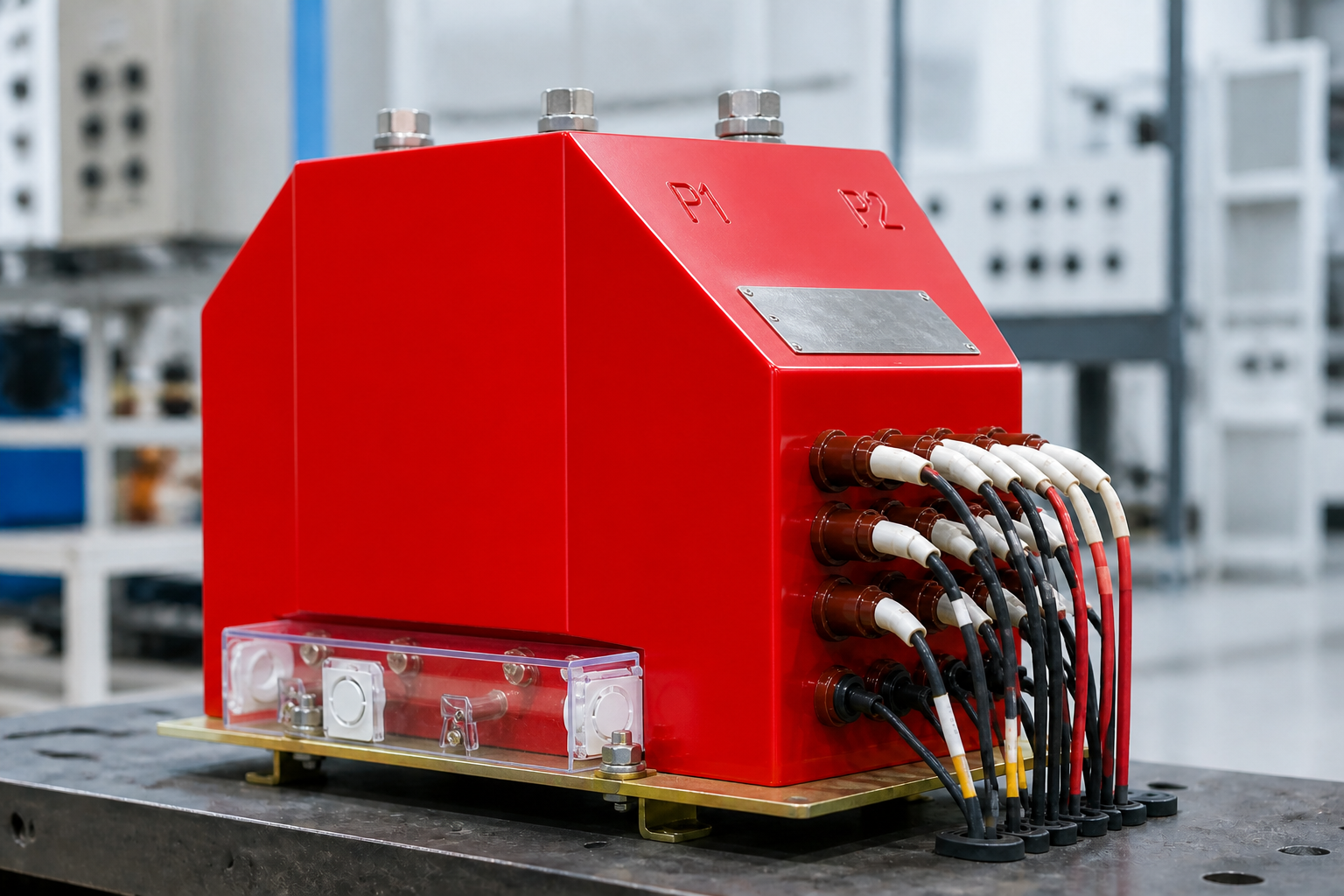
Counting the windings
On a voltage transformer diagram the circles indicate the primary and secondary windings. Discount one for the primary, and the remainder are secondaries. Two circles means one primary and one secondary. Three circles is usually a three-phase, five-column unit: one primary and two secondaries, one star-connected and one connected as an open delta. A unit with three windings and four secondary groups carries a 100/√3 winding, a second 100/√3 winding and a 100 V winding; a five-circle arrangement adds an open delta on top of the four.
How it works
A voltage transformer is a transformer with a core, made up of primary and secondary windings, the core, and insulation. Applying a voltage U1 to the primary produces a flux φ in the core; by the law of electromagnetic induction a secondary voltage U2 then appears in the secondary winding. Changing the number of primary or secondary turns produces different primary-to-secondary voltage ratios, and so different voltage transformer ratios.
The open delta in service
Consider a three-phase combined unit with a primary rated 10/√3 kV and two secondary windings rated 0.1/√3 kV. The star-connected winding is used for metering; the other is connected as an open delta and used to detect zero-sequence voltage. When the three phase-to-earth voltages are balanced, the vector sum is zero and the open-delta voltage is zero. When one phase goes to earth, the vector sum — the open-delta voltage — equals the line voltage, which is used to raise an alarm. When one high-voltage fuse blows, the vector sum equals the phase voltage, again used for alarm.
Why VTs are built the way they are
The characteristics that follow from all this are small physical size, small capacity, a large ratio — secondaries are standardised at 100 V and 100/√3 V — and low ratio error and phase-angle error.
Single, dual and three-winding VTs
The terminals on a VT tell you how many secondary windings it carries. A single-winding VT has one secondary pair (1a-1n) feeding one function. A dual-winding VT adds a second pair (2a-2n) so metering and protection run on electrically separate windings — a short circuit or a fuse operation on one circuit cannot drag the other down. A three-winding VT adds a tertiary winding (da-dn), almost always connected in open delta, dedicated to earth-fault detection. Each winding has its own rated burden and accuracy class printed on the nameplate, because each one serves a different instrument group.
How to read the winding diagram
Manufacturers draw each winding as a circle with its terminal labels: the primary winding, then one, two or three secondary circles. Count the circles, read the labels, and the function is clear: one circle = measurement only; two circles = measurement plus protection; three circles = measurement, protection and residual voltage. The open-delta winding is recognisable by its special terminal naming (da-dn) and by the connection instruction "open delta" on the diagram. Before wiring, match every terminal on the physical unit to the diagram — the labels are the only guarantee that the metering, protection and earth-fault circuits land where they belong.
Frequently asked questions
Why does a VT have two secondary windings?
So metering and protection are electrically independent: one winding feeds the meter, the other feeds the relays, each with its own burden and accuracy class.
What is the open-delta voltage on a healthy system?
Near zero. The three phase voltages cancel in the delta because the system is balanced; only an earth fault or a blown HV fuse produces a residual voltage.
What happens on an earth fault?
The phase voltages unbalance and the open-delta terminals show roughly 100/√3 V (for a 100 V secondary), which drives the earth-fault alarm or trip relay.
Can two VT secondary windings be paralleled?
Only identical windings with the same ratio, phase and polarity — and in practice it is rarely needed. Keep each winding feeding its own circuit as the design intends.